Have you ever wondered how we safely measure high currents in power systems without damaging our instruments? That’s exactly why we use a current transformer, or simply CT.
In this blog, we’ll walk you through what a CT is, how it works, and the important parameters and accuracy classes that define its performance. Stick around to the end—you’ll come away with a clear understanding of how CTs make modern electrical systems safer and more reliable.
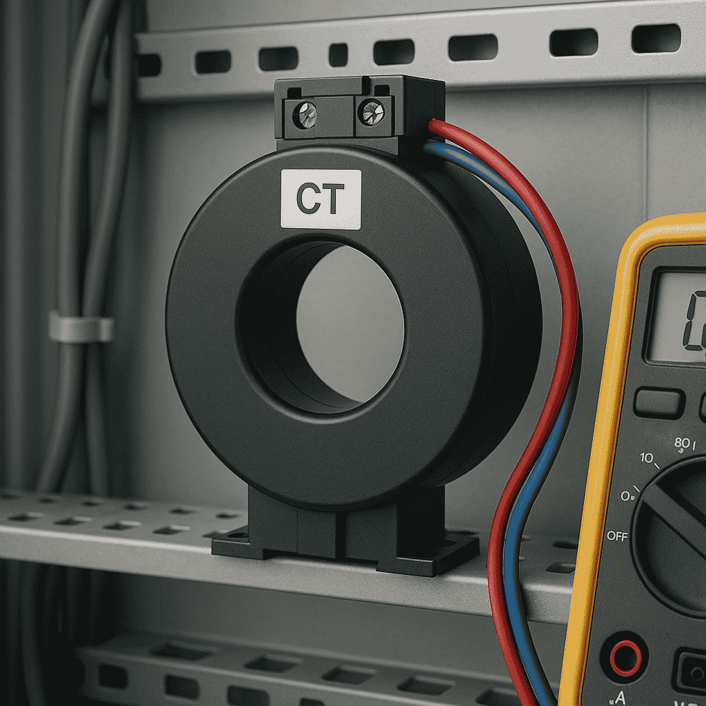
What is a Current Transformer (CT)?
A current transformer is a special type of transformer. But unlike power transformers that step up or step down voltages, a CT is designed for measurement and protection. It doesn’t deliver power. Instead, it scales down high currents to small, readable values—typically 5A or 1A—so we can monitor them safely.
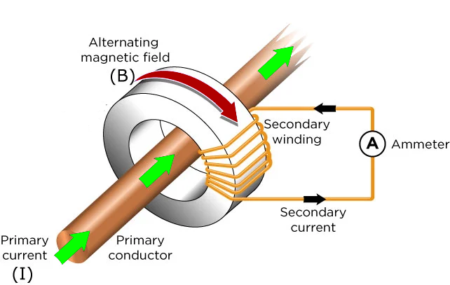
The principle is straightforward:
- The primary side carries the main high current, often just a single conductor passing through the CT window.
- The secondary side produces a smaller current proportional to the primary.
For example, if the CT ratio is 1000:5, and the primary current is 1000A, the output from the CT will be 5A. It’s like the CT is “whispering” the current value to the meter—if the meter reads 5A, it actually means 1000A is flowing through the primary.
Key Parameters of a CT You Should Know
1-Rated Secondary Current
This is the standardized current output—either 5A or 1A—when the CT is fully loaded.
2-Rated Extended Current Rating
This tells us how much the CT can handle above its rated current without saturating.
For instance, a 120% rating means the CT can operate normally at 1.2x its rated current.
3-Accuracy Classes and CT Types
Accuracy matters when it comes to CTs—especially depending on whether the CT is used for metering or protection.
Common Accuracy Classes:
0.2S, 0.2, 0.5S, 0.5 – Extremely precise. Ideal for tariff and revenue metering where every milliamp counts.
5P, 10P – Used for protection purposes. Less accurate under normal loads, but can handle high fault currents.
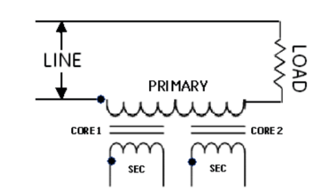
Fun Fact: A single CT can have multiple cores—one core for metering, another for protection (sometimes even two protection cores!). That’s not unusual in practice.
4-Understanding Accuracy Limit Factor (ALF)
Let’s decode a marking like 5P10:
- 5 = The maximum allowed composite error in percent.
- P = This CT is for protection.
- 10 = The accuracy limit factor (ALF).
So, a 5P10 CT remains within 5% error even if the current spikes to 10 times its rated value. For instance, if the rated current is 1000A, and there’s a fault of 10,000A, the CT still works accurately—within 5% error—and doesn’t saturate.
5-Instrument Security Factor (ISF)
Now let’s compare ALF with ISF—the Instrument Security Factor, important for metering CTs.
In high fault conditions, metering CTs should saturate intentionally to protect sensitive meters.
So, in a high current fault:
- A high ISF value means the CT saturates, limiting the current flowing to the meter.
- This protects the meter from damage, ensuring you only need to replace the CT—not the whole meter.
So ALF is for protection CTs—accuracy at high currents, while ISF is for metering CTs—saturates to protect meters.
CT Marking Example
Let’s break down: 5P20 15 VA
- 5 = 5% composite error
- P = Protection class
- 20 = ALF (accurate up to 20x rated current)
- 15 VA = Burden – The total load on the CT secondary (relays, wiring, etc.)
Important Terms you should understand
What is Ratio Error?
Ratio error is the percentage difference between the actual CT output and the ideal output.
For example, in a 1000:5 CT, we expect 5A on the secondary when 1000A flows in the primary.
But if the CT outputs 5.1A, it introduces a ratio error
Ratio Error (%) = [(Actual Secondary × Rated Ratio – Primary Current) / Primary Current] × 100
The smaller the error, the more accurate the CT—this is crucial for billing and energy accuracy.
Composite Error
This is a combination of all errors under high current, including:
- Ratio error
- Phase error
- Core magnetization effects
- Burden (load) effects
Protection CTs are measured using composite error, and the IEC standard allows up to 5% error for classes like 5P.
Example: If you see 5P10, it means that at 10x rated current, the total error (including all the above) must not exceed 5%
Phase Displacement (Phase Error)
This is the angular difference between the primary and secondary currents. It’s especially important in metering, because a phase shift—even with the correct current—can mess up power and energy calculations, especially at low power factors.
That’s why IEC standards define strict limits for phase displacement across classes like 0.2, 0.5, and so on
Final Words
- A CT is not a power transformer—it’s built for measurement and protection.
- It scales down high currents (e.g., 1000A ➝ 5A) for safe monitoring.
- Key specifications include:
- Rated secondary current
- Extended current rating
- Accuracy class (e.g., 0.2, 5P)
- ALF (Accuracy Limit Factor) for protection
- ISF (Instrument Security Factor) for metering
- CTs may have multiple cores for different uses.
- Key errors to understand:
- Ratio Error
- Composite Error
- Phase Displacement
Whether you’re designing a substation or billing a customer, understanding CTs isn’t just helpful—it’s essential