
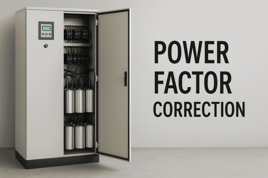
In today’s industrial and commercial environments, energy efficiency is crucial for reducing costs and ensuring smooth operations. One of the key components used to improve energy efficiency is the APFC Panel, or Automatic Power Factor Correction Panel. These panels are designed to improve the power factor of an electrical system, ensuring optimal performance and reducing energy costs.
In this blog, we’ll explore the purpose of APFC panels, their key components, and provide a step-by-step guide to wiring an APFC panel.
1. Purpose of APFC Panels
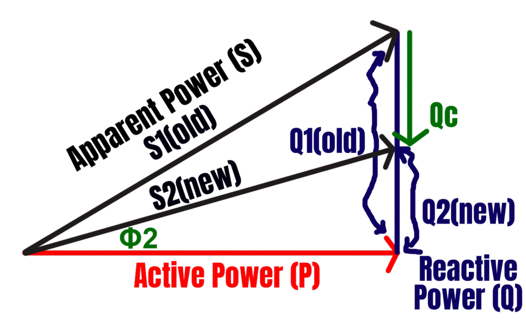
Power factor is the ratio of active power (P) (used for actual work) to apparent power (S) (total power supplied). A poor power factor means that more apparent power is needed to perform the same amount of work, leading to inefficient energy consumption, higher energy bills, and penalties from utility companies. This is where APFC panels come into play. These panels automatically adjust the system’s power factor by switching capacitor banks on or off, based on real-time needs.
An efficient power factor close to unity (1) not only reduces energy bills but also improves the longevity of electrical equipment, like transformers and motors, by reducing strain.
As you can see adding capacitors to your load will decrease the total reactive power which will decrease the apparent power and will improve power factor.
2. Components of APFC Panels
APFC panels consist of several important components that work together to monitor and correct the power factor:
- Capacitor Banks: These capacitors are the key elements used to counteract reactive power. They are switched on and off to adjust the power factor.
- Power Factor Controller: The controller measures the system’s power factor in real-time and automatically manages the switching of capacitors.
- Relays and Contactors: Controlled by the power factor controller, relays and contactors manage the connection and disconnection of the capacitor banks.
- Current Transformer (CT): Monitors current in the system and helps the controller decide when to activate or deactivate capacitor banks.
- Circuit Breakers/Fuses: Ensure the protection of the electrical circuits and components inside the APFC panel.
- Display Meter: Provides essential data like power factor, voltage, current, and capacitor bank status in real-time.
3. How APFC Panels Work
The APFC panel works automatically, with minimal manual intervention. Here’s how:
- Continuous Monitoring: The power factor controller constantly checks the power factor of the electrical system. If it falls below a predefined threshold (typically 0.9 or lower), the controller engages the capacitors to provide reactive power and improve the power factor.
- Switching Capacitors: Capacitor banks are switched on in steps based on the system’s needs. If the system requires more reactive power, additional capacitors are activated.
- Automatic Adjustment: The panel ensures that the power factor is constantly maintained close to 1 (unity) by adjusting the capacitors based on real-time electrical load conditions.
4. APFC Panel Wiring Guide
Let’s dive into how an APFC panel is wired. This step-by-step guide explains the main connections and components used in the wiring process.
Step 1: Connecting the Supply
The power supply to the APFC panel is typically taken from the main distribution board. The panel is connected in parallel with the supply, meaning no direct load is taken from the panel itself. Instead, the APFC panel monitors and corrects the power factor by switching capacitors on or off.
Step 2: Current Transformer (CT) Installation
The current transformer (CT) plays a critical role in monitoring the system load. The wiring of the CT is vital: connect the P1 side to the supply and the P2 side to the load. The CT feeds load data back to the power factor controller.
Step 3: Capacitor Bank Sizing
Capacitor banks are sized according to the transformer’s rating. For example, a 1000 kVA transformer may require capacitor banks rated at 250 kVAR to 400 kVAR. The appropriate size is determined based on the load, typically between 25% to 40% of the transformer’s capacity.
Step 4: Wiring the Components
Once the power supply and CT are in place, you’ll need to wire key components:
- Bus bar connections: These connect the APFC panel to the main supply and allow the controller to monitor the system.
- Capacitor banks: Capacitors of various ratings (e.g., 12 kVAR, 25 kVAR, etc.) are wired to contactors, which manage the switching of these banks.
- APFC Relay: This is the core of the panel’s automation. The relay controls the capacitors, turning them on or off based on the system’s needs. The relay is wired to the CT for load data input and connected to each capacitor bank for control.
Step 5: Manual and Automatic Control
APFC panels are designed for both automatic and manual operation. In automatic mode, the power factor controller handles everything. However, switches can be wired for manual control in case the panel needs to be operated manually.
Step 6: Final Connections
The final step is to ensure all connections are properly made between the power supply, capacitors, relays, and the current transformer. Ensure that circuit breakers or fuses are installed for protection, and double-check all connections for accuracy and safety.
5. Benefits of APFC Panels
Using an APFC panel offers several key advantages:
- Cost Savings: By improving the power factor, APFC panels help avoid penalties from utility companies and reduce overall electricity consumption.
- Increased Efficiency: APFC panels reduce the load on electrical equipment, improving system efficiency and reducing wear and tear on machines like transformers and motors.
- Automation: With an APFC panel, there’s no need for manual intervention, reducing the risk of human error and ensuring that the system is always optimized for efficiency.
6. Applications of APFC Panels
- Industrial Plants: Manufacturing facilities that use a significant amount of inductive loads (motors, compressors, etc.) benefit greatly from APFC panels, as they help maintain an efficient power factor.
- Commercial Buildings: Large buildings such as malls and hospitals also use APFC panels to avoid extra charges due to poor power factor.
- Data Centers: Data centers rely on APFC panels to ensure efficient power usage and avoid penalties from utility companies.
Conclusion:
APFC panels are an essential component for industries and commercial buildings looking to optimize their energy usage, reduce costs, and extend the life of their electrical equipment. By automating the power factor correction process, APFC panels help ensure that power is used efficiently, with minimal waste. If you are considering improving the energy efficiency of your facility, an APFC panel is a smart investment.