
Continuity testing is a fundamental practice in electrical work, ensuring that the electrical path in a circuit is complete. It’s a quick and reliable method to check if a circuit is capable of carrying current. This test is essential for identifying faults in various electrical components such as fuses, contacts, cables, and more. Whether you’re troubleshooting a problem or verifying a new installation, continuity testing is an indispensable tool in maintaining the integrity of electrical systems.
What is Continuity Testing?
Continuity testing is the process of verifying that an electrical circuit or component has a complete path for current to flow. In simple terms, it checks whether two points in a circuit are electrically connected. This test is commonly used to ensure the functionality of electrical components like fuses, contacts, cables, switches, and wiring. A successful continuity test indicates that the component or circuit is intact and capable of conducting electricity, while a failed test points to a break or fault that needs to be addressed.
Tools Needed for Continuity Testing
- List the tools required for performing a continuity test, primarily focusing on the multimeter.
- Briefly explain the importance of using a properly functioning multimeter and ensuring safety during the test.
How to Perform a Continuity Test
Preparation:
Turn off power to the circuit to avoid any electrical hazards.
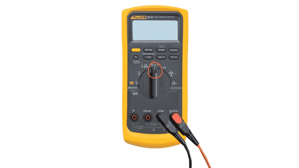
Setting Up the Multimeter:
Set the multimeter to the continuity mode (often indicated by a soundwave symbol).
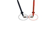
Explain how to correctly position the test leads (black to COM, red to VΩ).
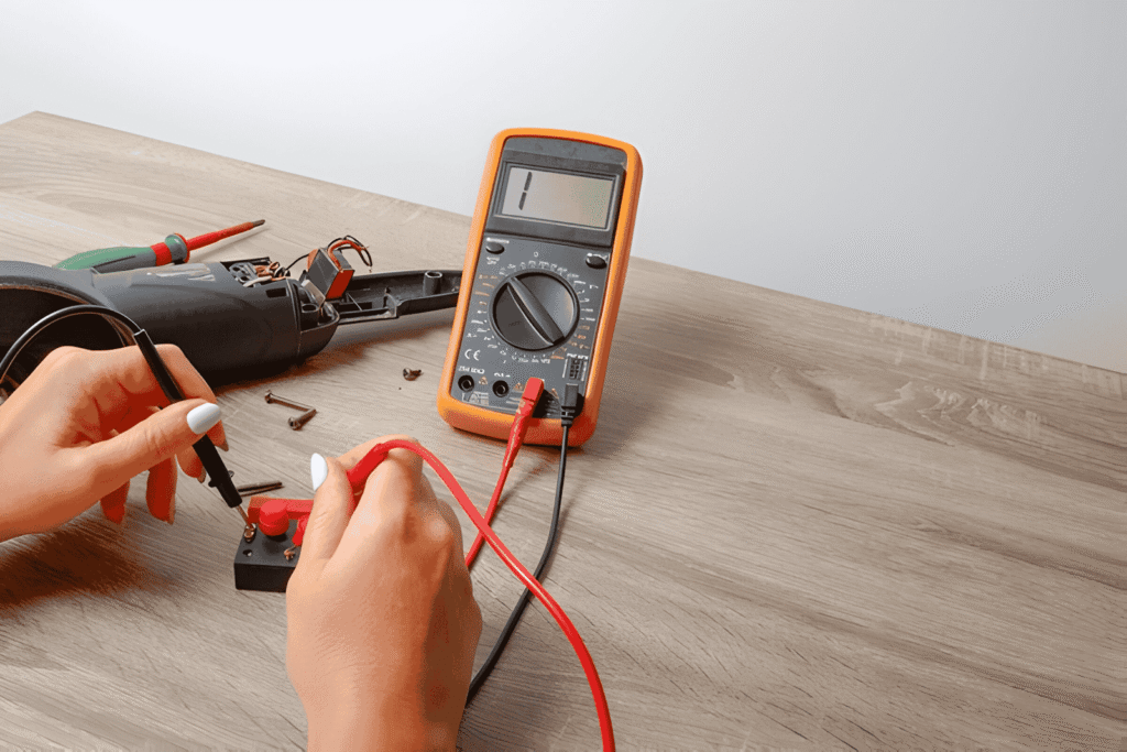
Performing the Test:
Touch the multimeter probes to the two ends of the circuit or component.
Explain the possible readings:
Continuous Beep/Low Resistance: Indicates a complete path.
No Beep/Infinite Resistance: Indicates an open circuit.
Interpreting Results:
Discuss what different outcomes mean for the circuit’s integrity.
Include tips for further troubleshooting based on the test results.
Common Applications of Continuity Testing
- Explain where and how continuity tests are commonly used, such as checking fuses, wires, switches, and PCB traces.
- Provide practical examples to illustrate these applications.
Tips for Accurate Continuity Testing
- Offer advice on avoiding false readings, such as ensuring good contact with the probes and avoiding testing in live circuits.
- Mention any common mistakes to avoid.
Conclusion
- Recap the importance of continuity testing in electrical work.
- Encourage readers to practice safe testing procedures and regularly perform continuity checks during installations and maintenance.